
CNC Mini-Mill Build
This project was made back in 2016, as it is now late 2021 and all I have is a photo archive I will do my best to expand on the detail the photos provide as much as possible.
This project is a small bench-top CNC milling machine, it’s a “gantry” style build where the bed is fixed and all the motion is provided by a moving bridge or gantry. This style machine is generally easy to build but is not as rigid and as a bed mill where the X & Y motion is provided by a moving table or bed, the tool only moves up and down in the Z axis.
I used a lot of 6061-T4 aluminium tooling plate as it is finished to a high standard and relatively cheap, ideal for this type of project. I had a Bridgeport knee milling machine which was manually operated and had a digital readout on it for accurate measurements/positioning.
The frame was made from 80×40 & 40×40 extrusion which is very versatile and in the small lengths needed here, very rigid. The bed of the machine was a cast iron plate from an old printing press – this was ground flat to a very high degree and cast iron is an excellent material for this use.
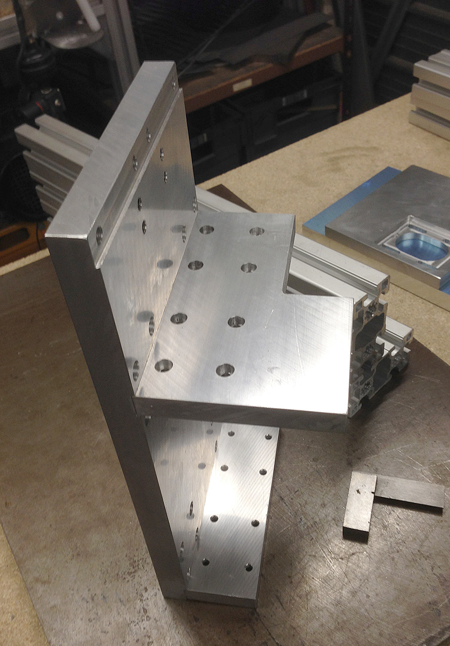
I had a starting help with the design from a guy that makes them to order, this removed a lot of the guesswork and sped things up a lot. The secret was to mill slots or registers for the extrusion where it meets a flat plate, this increases rigidity massively and can be seen in the photos.
Motion was provided by 4Nm stepper motors connected with toothed belts and gear reduction, control was to be be by a PC running software called “Mach 3”. The motion was built with linear rails and blocks, I chose “HiWin” products here as they are a good name and not too expensive. Movement was transmitted from the motors to the axes via ball-screws.
Building the Mill


Testing the Motion

Production Parts Being Made

Engraving on the Mini-Mill
With the right tooling it can also do engraving. The accuracy is stunning and the quality is very high.


Conclusion
About a year after I made the mini-mill, I realised I had stopped using the large Bridgeport mill. The decision was made to strip the Bridgeport and fully convert it to CNC operation – this would make the mini-mill surplus as the Bridgeport was more than capable of doing everything the mini can and it would save valuable floor space if I sold the mini-mill.
It was soon sold to a clockmaker who wanted it for milling gears and engraving, the cash raised went a long way to paying for the Bridgeport conversion – this is covered in another build log.