
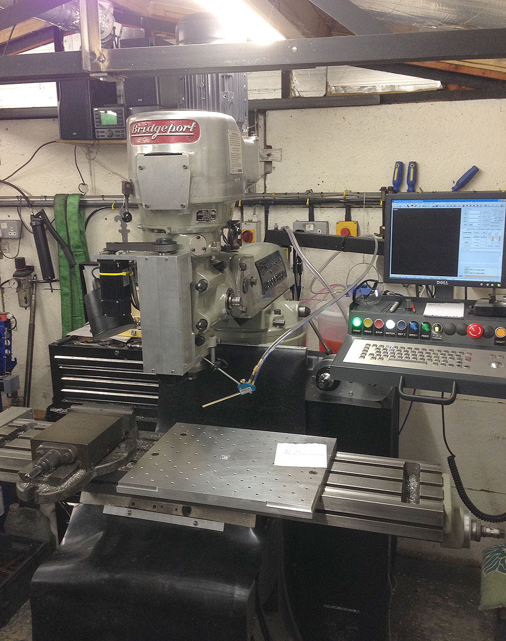
Bridgeport Mill CNC Conversion
The date is May 2016 and the decision was made to convert my manual Bridgeport knee mill to full CNC control.
It has served me well, having helped build two large scale traction engines and a multitude of other projects and production parts for my home business but I had ideas for other projects that just could not be made manually.
I did a lot of research before going in with the spanners, the workshop was too small for all but the smallest commercial CNC milling machines as it just did not have the headroom needed, plus the commercial offerings all had very small tables.
The Bridgeport had the size I wanted with the 48″ bed and it was in good mechanical condition generally.

Specifications
I had decided to go with a full rebuild and use the best quality parts I could afford on it. The list included 750W AC servos on the X & Y axis and the knee, 500W AC servo on the Z axis, an uprated 3Hp main drive motor with 1:1 drive, new ball-screws on X & Y axis, an industrial grade CNC controller by CS-Labs and the front-end driven by Mach-3 software – Mach-3 was getting a little old in 2016 but I was familiar with it and it has a good support backing.
The Strip-down


Repainting and build-up…


Axis Drives


Limit Switches
Limit switches were a must-have – the servo motors and drive reduction meant that there was enough power available in a bad situation to rip the ends off the table!


Wiring and Testing
The wiring was lashed together on a sheet of scrap MDF. Partly for testing and partly to judge the layout for final cabinet build.

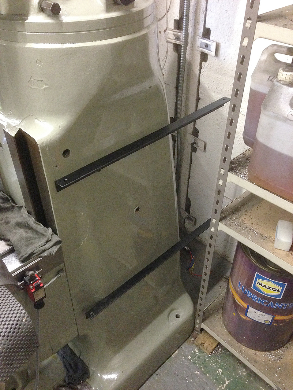
The Z Axis
The Z axis is the hardest part on these conversions – the quill drive and head is not built for automation at all. Various options have been done before and I chose to drive the axis by connecting a ball-screw to the old quill-stop mounting. The motor is a 500W AC servo and drive is via 20mm toothed belt at 2:1 ratio.
The drive mount bolts on to existing points at the top and a hole drilled & tapped in the lower head reference surface.


The weak point in the Z drive is the connection to the quill/spindle tube. The first attempt broke very quickly so I had to machine up a new, stronger version. This drive setup is hard on the ball-screw & nut as it places a lot of angular load on them and ball-screws do not like that.


The Cabinet


Cabinet wiring is one of my favourite parts, I have made several during my work days but this was the biggest. Servo drives are top-left, motor VFD’s are top-right, CNC controller in the middle and the PC for the display at the bottom. Behind the PC are the safety protection fuses and breakers plus wire loom connections.


Final Testing and Debugging

The High-Speed Spindle Attachment
When I made the conversion, I wanted to be able to sell my mini-mill to recover floor space. This meant I would need a high-speed spindle on the Bridgeport. I devised a mounting bracket to enable a 24,000rpm water-cooled engraving spindle to be fitted to the main Z axis of the Bridgeport.
Having a working CNC mill now made the build easy and very fast, 6061-T4 aluminium tooling plate was used as the surfaces were finished to a high standard.


When in use, the attachment mounts onto the quill/spindle, the small spigot is clamped in a collet to give extra stability. The main drive motor is locked-out and the drive signal is switched to the high-speed motor drive.

For engraving use, a large sub-table is mounted on the main table, it was drilled and tapped with a grid of M6 holes for clamps.


The Knee Drive
The knee drive was added a while after the main build, another 750W AC servo and 4:1 drive was used. This was programmed to take the tool length offsets so it only moved when changing tools or setting up the job.

Swapping the Spindle
The spindle was changed after a bit of use – the original R8 taper fit spindle was swapped for a QC30 spindle. The QC30 is compatible with modern BT30 tooling which means I can use the tool table and preset tool offsets as they are in much larger machines.


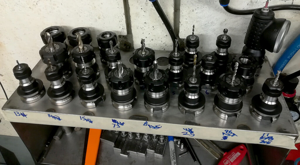
Tooling Up
Now that I had a BT30 spindle, I could use standard tooling mounts which offered repeatable position for the tools – the old R8 spindle collets were not repeatable which meant jobs had to be programmed and run one path at a time. Repeatable position tooling means I could run the job as one process and change tools where needed.


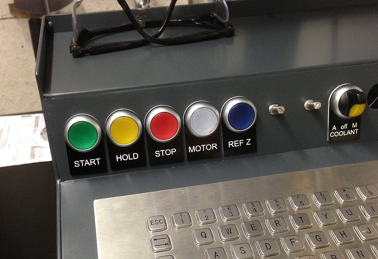
The Software
I wrote completely custom user interface screens in Mach-3 – these featured only the exact functions I needed to do what was required, no bells and whistles.


Some Videos
Afterthoughts and Notes
The CNC controller I used has something called “Encoder homing” – this uses a combination of mechanical limit switch and electronic encoder for setting the home/zero position of each axis. Using a switch alone is not very accurate but using encoder homing allows you to return to a job at a later point while it’s still set up and continue working on it after having turned the mill off!
Converting a Bridgeport mill to CNC most certainly does not increase its resale value to the point where you can recoup the costs involved in doing so. I knew this at the start and was OK with it, it’s worth remembering though.
The parts I used are fairly expensive – the ball-screw kit came from the USA and cost nearly 3x what I paid for the Bridgeport! The CNC controller was industry standard kit but being that good made the job so much easier as it just worked without any messing about, support is also there if needed.
After conversion, the mill went on to produce work for 4 years, at which point I retired and sold-up. It made far more money than it cost to convert 😉 and the person that bought it got an absolute bargain.