
The Stuart-Turner Beam Engine
This project was made in 2006 as a practice run and to increase my engineering skills prior to starting the 3″ traction engine build.
The kit comes as a heavy box of castings and metal parts. No engineering is pre-done and all parts are supplied in a rough cast or cut state, vacuum sealed on to a card backing.
The quality of Stuart-Turner castings is extremely high and the more difficult smaller shapes are cast in brass or gunmetal.
This is one of the largest kits they supply that come complete with all fixings, the larger ones require you to make or find all of the nuts and bolts too.
The first thing to do is to identify all the metal against the plan. As there were so many parts, I put each bit in a labelled bag so it could be found easily later.
Then you need to formulate a plan of attack for each bit, some of the items require quite a bit of thought and several cups of coffee as they are very odd shapes.
Next you need to pick a starting point and make another coffee.
I chose the base pedestal and the crankshaft outrigger support as they looked quite simple and were relatively large lumps.
Once these are done, all of the other parts fit onto them so you can then choose an area to work on and fit it against the base as as you go.
Many of the parts fit into other parts very closely, so it is important that they are made in the correct order as it can be very hard to make a hole smaller once it is drilled!
The pedestal & outrigger
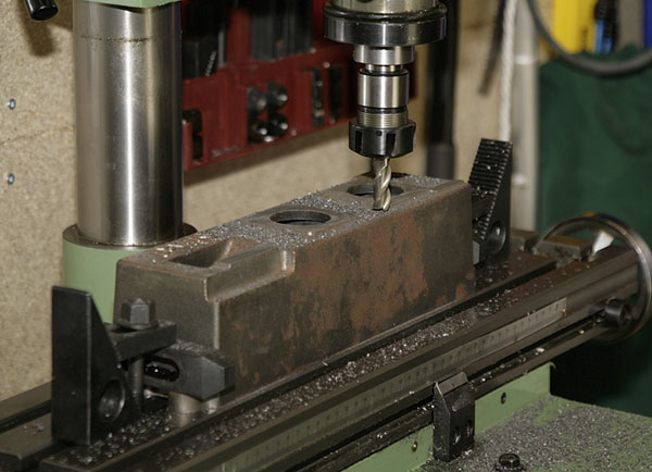
The pedestal set up on the mill for surfacing the top registers. The pedestal underside has already had a light
milling to clean up the casting and give a firm, flat clamping surface.
Only the minimum amount of material needs to be removed and it was all done in one pass. The height setting must not be moved as the outrigger must be exactly the same height…
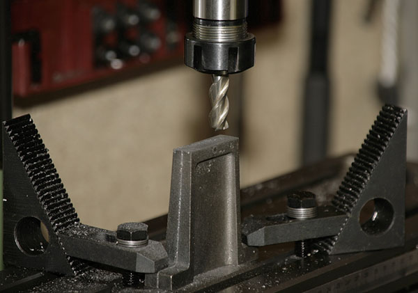
The outrigger being milled. Again, the base of this part was done before the final cut was setup for the
top of the main base. This ensures that both parts are the same height. Not very secure clamping here so the cut was taken very carefully and along the surface not across it.
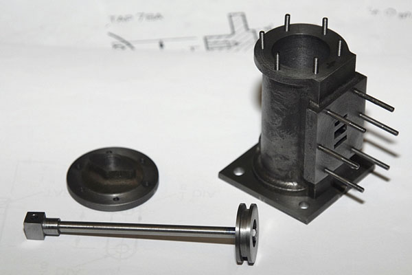
The support column

The column was setup in the lathe for the inner surfaces of the top and bottom plates and the outer surface of the bottom plate to be machined. The spigot in centre of the base plate was left on as there is a large hole in the main base for it. The base plate was machined first as the top plate had to be a set distance from it.

The column in the mill having it’s top surface machined to dimension. Setting the column squarely to the direction of cut was the hardest bit. I could have used a longer mill but did not have one so I had to set locating blocks to allow me to rotate the column half a turn and get it back in the same position.
The top of the column having the slots cut for the entablature arms, these support the parallel linkage for the piston rod. I used a narrow slot-drill for these and set the width of cut using the table traverse scales. The end result was a perfect fit 🙂

The base, column and entablature arms being test fitted.
The flywheel

The flywheel in the 4-jaw having it’s outer surface machined. The center hole has already been bored and the front face cleaned up, all at the same setting so that the surface runs true when finished.
It’s very messy stuff cast iron, and I forgot to cover the lathe bed so I had to spend the next half hour
cleaning all the abrasive grit off of it 🙁
The flywheel measures 7″ so it was easier to mount in the 8″ 4-jaw rather than on the 11″ Faceplate.

The finished flywheel and a couple of bearing blocks.
The beam & bearing blocks

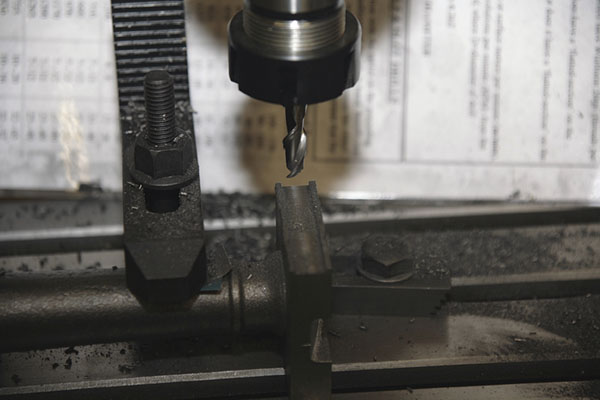
The beam on the faceplate being bored. The edges were finished by hand filing, pilot holes for the shafts were drilled on the mill using the table feed dials for measurement.
A couple of bearing blocks with the flywheel. Final cleaning up still needs doing and the bearing caps need drilling for imitation clamping bolts to give a better appearance.
The cylinder block
The cylinder block being bored. The end face has already been turned at this setup so that it is true to the bore when finished, this will be the piston rod end of the cylinder.
The ugly lump of metal in the left foreground is a counterweight to balance the heavy angle plate that I used to mount the job. I should have got a much bigger boring bar for this job as the extension needed to get through the cylinder was far too much for the little bar I had. But, with a little patience, it did the job nicely.
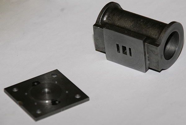
The part finished cylinder and bottom cover plate. This cover is used to bolt the cylinder down to the base of the engine.
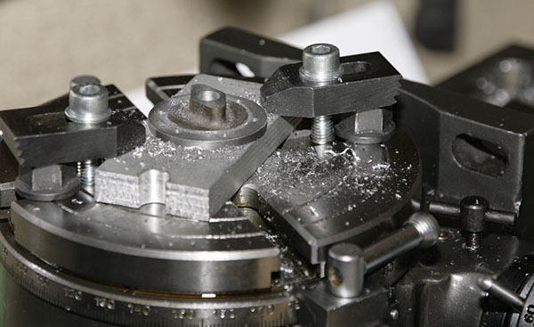
The top cover mounted on the rotary table having it’s six equally spaced mounting holes drilled. It is fixed to a scrap mounting plate with a screw through the centre hole which is then bolted to the drill. Setting up took ages but the results are near perfect so it was worth it.
The cylinder with piston and cover plate. The groove in the piston is for a rubber ‘O’ ring.
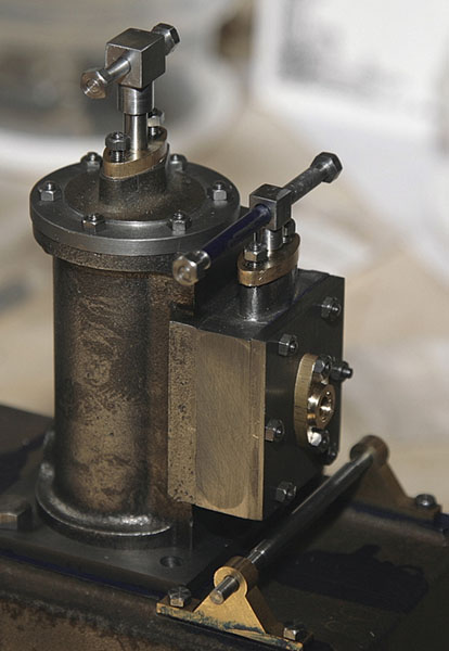
The finished cylinder complete with packing glands, steam inlet flange and valve chest
The valve chest & cover
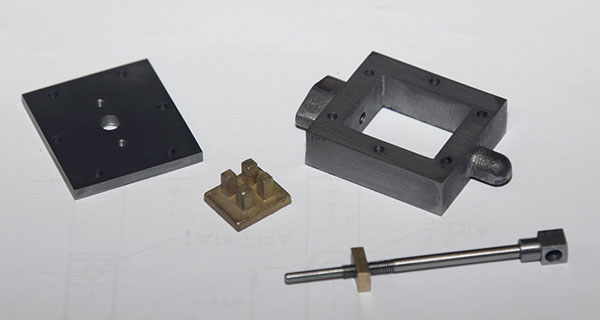
The finished valve chest, valve, push rod and chest cover. Mostly lathe and milling machine work, details were hand-filed.
The connecting rod
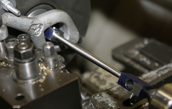
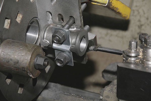
The connecting rod between centres being “fishbellied”. This item is one of the more complex ones, being cross-drilled, bored, turned and eventually hand shaped.
The “fishbelly” effect is really two opposing tapers of about two degrees inclusive, one end was turned and the rod flipped over for the other end. The surface was then filed in the lathe to blend the tapers together.

One end finished, the other half roughed-out ready for the yoke to be slit.
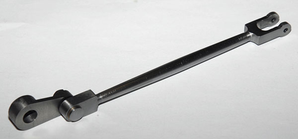
The finished con-rod complete with the crank and crank pin. This item was one of the most complicated parts of the kit. The big-end also has a bronze bush press fitted into it.
The drive pulley
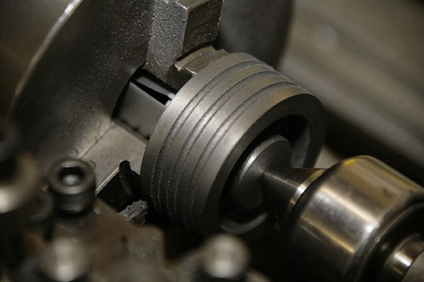
The belt grooves being turned in the face of the pulley. I had to grind up a cutter specially for this as they are half-round grooves. Spacing was taken care of by using the top slide to advance the cutter by an equal division of the face width.
The bore was then drilled and bored to fit the crankshaft nicely. Then it was mounted on a piece of scrap shaft and the back face was finished.
Crankshaft & bearings
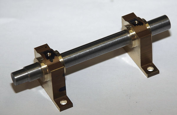
The crankshaft and main bearings. The tops of the bearing blocks are drilled and tapped ready for the oil-cups. Final finishing still needs to be done on the bearings. The bearings were turned in the four-jaw chuck on the lathe.
The finished engine

As it was on 17/06/2006, all that remains to be done is to make the eccentric strap and sheave, parallel motion linkage and then to clean up all the rough edges, test and paint it. Then it needs a nice polished base to mount it on.

30/06/2006 – The finished engine. Mounted on a polished wood base. It worked first time and ran even better after a little fine tuning of the valve timing.

The valve linkage.

Watts parallel motion and the beam.

The crank and eccentric.
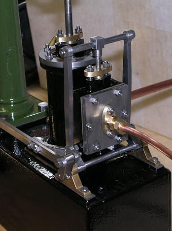
The cylinder and valve chest.
It is a fascinating engine to watch running, it was worth building just to study the action of the Watts’ parallel motion ! I will have to find a suitable place to display it now.
A lot of skills were learnt while making it including close tolerance turning, milling, accurate marking out and how to extend my patience!