
Tesla Coil 3 – OSVTTC
Early days
This will be my third coil, if I ever get it working !
As before with the Vacuum Tube Tesla coil, this project uses a very large radio transmitter valve in place of the spark gap in the standard coil. This time I am trying to drive it with a variable frequency oscillator, which can be “tuned” to the resonant frequency of the coils. It only uses two coils, the primary and secondary coil. It is a far more complicated design and may never work, but you don’t know if you don’t try!
+++Primary Coil+++
25 Turns 2.5mm copper cable wound on a 15cm former.
+++Secondary Coil+++
1000 turns of 0.315mm enammelled copper wire on a
68mm pvc former.
+++Oscillator+++
Variable between 150 & 500kHz, 300v p-p output.
+++Power Supply+++
2.1kV 1300W Microwave oven transformer for the main tube plate supply
2.1kV 1300W Microwave oven transformer for the main tube screen grid supply
12v 12A Transformer for the main tube heater supply
240v + 6.3v Transformer for the oscillator and grid bias
+++Tank Capacitor+++
1880pF 20kV Ceramic capacitor rated at 60kVAr
+++Control Box+++
Standard line filter at input, earthed to supply ground
275v MOV across supply outputs
Variac power control
Input ‘Live’ and ‘Ready to fire’ warning lamps
Output voltage and current meters
Key operated safety switch
Two simultaneous press-to-fire buttons and a long extension lead !!
The tube
The GU-81M Tube. The picture is deceiving, it measures 260mm tall and weighs in at 1kg !
It’s original use was for Russian military radio transmitters, 700w of pure high frequency electrical mayhem ! It’s the same unit I used in my first VTTC.

The circuit
The components to the left of C5 form the oscillator circuit, C5 is the coupling capacitor and the mid-section is the power amplifier stage. The output of the oscillator is around 100v p-p and a sort of rough sine-wave. The main tube needs around 300v p-p though and the power amp boosts the signal to this level. C3 is the coupling capacitor for the main output tube, I intend to have a few feet of screened cable here to give me some safety distance from the output, to the right of C3 is the Tesla circuit itself. The lower, ground rail is connected to the main ground line. This project requires no less than four different supply voltages, all of them termed as “High Voltage”.
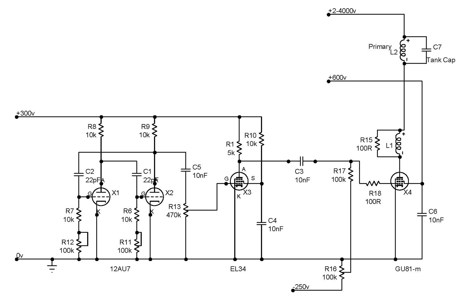
C1/C2 – 22pF.
C3/C4/C5/C6 – 10nF.
R1 – 5k 20W.
R13 – 470k 1W Potentiometer to control the amplifier grid drive level.
R6/R7 – 10k 1W.
R8/R9/R10 – 10k 11W.
R11/R12 – 100k Dual Ganged Potentiometer.
R17 – 100k.
R16 – 100k Potentiometer for adjusting the control grid bias level.
R18 – 100ohm Grid stopper.
X1/X2 – 12AU7 Tube.
X3 – EL34 Tube.
X4 – GU81-m Power tube.
R15/L1 100ohm 10w resistor with 15 turns of insulated wire wound over.
I will post some oscilloscope pictures as soon as I have some.
The power supply
K1 / K2 – Microwave oven transformers, 2100v output.
K3 – Mid power supply transformer for Oscillator, grid bias and small tube heaters.
K4 – 12.6v 10A Filament transformer for output tube.
C1 / C2 / C3 – Microwave oven capacitors.
D1 / D2 – Microwave oven diodes.
C4 / C5 – 470uF Smoothing Capacitors.
C6 / C7 – 0.1uF Filament Decoupling Capacitors.
R1 / R2 – 220k Bleeder Resistors.
D3 / D4 / D5 / D6 – 1N4007 Rectifier Bridge.
Yes, thats 4 large and heavy power transformers ! K1 & K2 are supplied via individual variacs so I can control the output tube parameters fully. The bleeder resistors are there for my safety while testing. Should suck a few watts when I power the beast up 🙂

The oscillator
The oscillator and pre-amp unit nearing completion. The small valve is the 12AU7 twin triode used as an oscillator and the other is the EL34 pentode used for the power amp.
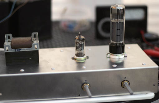
The controls on the front are for frequency and output level, on the rear is the bias control for the main tube grid bias.

Not much in it really ! Power supply is at the bottom, in the middle is the oscillator and the amp is at the top.
The secondary coil
The freshly wound secondary coil. The coil former is 68mm pvc pipe, dried, wound and varnished three times. As before, the winding jig was made up of junk box stuff, this time I used a battery operated drill to turn the former, which was much better. Total winding time was 30 minutes. Once wound, I switched back to the slow mains operated motor for the varnishing coats.

I used the same coil as for my VTTC design.
The tank capacitor
As before, four 470pF 20kV 60kVAr Capacitors, connected in parallel for a total value of 1880pF. They are quite large, the total length of the unit is around 420mm and weighs around 2kg !

I have connected them with 25mm x 1.5mm aluminium strips.
Bench-testing
Bench testing the beast…

On the left is the power supply area, two 2100v microwave oven transformers, a 12v 12A heater transformer, level shifter diodes, capacitors and one of the control variacs. Bottom right hand corner shows the oscillator unit, top right hand is the primary and secondary coils. In the middle is the main tube, tank capacitors, filter capacitors and power meters for plate volts and current and screen-grid volts and current. This birds-nest lash-up is easily capable of putting out enough power to kill so it has to be treated with the utmost respect, you really will only get one chance when mucking with this sort of power!! Then there is the fire risk and so-on, it’s not a past-time to be taken lightly.
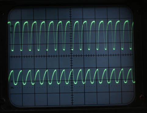
Test results 1
11/08/2005 – Testing the oscillator.
This part of the project actually worked first-time ! The first oscilloscope picture shows the oscillator output at the bottom and the power amp outout at the top. Voltage level shows 100v/cm, this is at the lowest frequency and clearly shows the poor waveform associated with this simple circuit design. The top waveform is more square-wave like due mostly to some severe clipping. It would most likely sound absolutely horrible as a sound amp but all i need is to switch the main tube on and off quickly, so it should work.

This picture below shows the same outputs again, but this time at it’s maximum frequency of around 500kHz. Note the change in waveforms.
Altogether a satisfying project on its own, now to build the noisy part !
Test results 2
20/08/2005 – Debugging the coil.
After lashing the coil and main tube together on a chipboard base, i carefully applied power to all the right places and….
Nothing !
Oh dear. I thought.
After a lot of headscratching and email burning between the members of the Tesla group, I decided to strip it down an start again. It turns out that I had inadvertantly shorted the tube plate straight to the power supply, bypassing the primary coil altogether !
If I were using silicon devices, I would no doubt have a big pile of junk on the table by now, but Valves being relatively indestructible, it did start working when I fixed the error. First output was pretty small, about 1 to 2 inches but at least the device worked, and the oscillator could be easily tuned to the resonance of the coils. Outside this point, there is no output at all.
Test results 3
22/08/2005 – Further tuning.
I gave the coil a lengthy run to see if anything blew up, and it didn’t !
Then it was time for a full power run, chair was moved back a bit 🙂 and the knobs were all twiddled to their relative maximum settings, it’s not simply just a matter of whacking them all up to max, as this power supply could easily blow the tube.
The output was nice and hot and noisy with 3 – 4 inch streamers. But overall it was not realy good enough considering that the setup was burning a horrendous amount of mains power ! Time for some fine tuning.
The primary coil was raised up 2 inches and the connections reversed. This time it managed 4 – 5 inch, sword-like streamers using much less power, so I can eventually push it even further. The downside was that it made it harder to adjust the oscillator into resonance, but is was still possible and, once there it was stable.
This was much more satisfying, it was also much louder !
The radiating power of this coil is quite impressive too, an open oscilloscope lead can easily pick up 50v of radiated RF power at over three feet away, fluorescent tubes glow brightly two feet away and my calculator blew itself up while I was sitting there trying to work out the power figures ! (sadly, it never recovered)
This is basically an AM radio transmitter, which bungs out large amounts of noise at around 450kHz, so it’s probably not a good idea to run it for long periods 🙂