
Tesla Coil 2 – VTTC

Firstly, this site was not intended to introduce you to the scientist and inventor by the name of Nikola Tesla (pictured left), so I have not bothered to add an introduction to him, if you want to find out more about this great man, try a web search on his name, you really will be amazed at how our lives are affected by his inventions.
Secondly, Tesla Coils by their very nature are potentially deadly pieces of apparatus, both to living beings and other electrical appliances !. They are easily capable of generating high frequency, high voltage discharges in the range of 1 to 20+ feet !!. If struck by one of these discharges, you can suffer serious RF burns to the inside of the body which can take surgery and a very long time to heal, you may not feel it because of the high frequency, but the damage will be done.
They are definitely not toys and should only be constructed by people with at least some knowledge of electricity, high voltages and spark discharges. If you choose to copy any of my design solutions, you do so entirely at your own risk and must accept the consequences of doing so.
The beginnings
This will be my second coil build.
The vacuum tube coil uses a very large Russian radio transmitter valve in place of the spark gap in the standard coil. It runs as a self controlled oscillator, continually charging and discharging the tank capacitor into the primary coil. They use three coils, the primary coil, the feedback coil which controls the rate of oscillation and the secondary coil. They run at lower voltages and much higher frequencies than spark gap coils and produce shorter, spiky discharges from a much smaller topload.
+++Primary Coil+++
25 Turns 2.5mm copper cable wound on a 15cm former.
+++Secondary Coil+++
1000 turns of 0.315mm enammelled copper wire on a
68mm pvc former.
+++Feedback Coil+++
20 Turns thin wire on the same former as the primary coil,
mounted 1cm below,
+++Power Supply+++
2.1kV 1300W Microwave oven transformer
12v 12A transformer for Vacuum Tube Heater Supply
Standard line filter at transformer supply, earthed to RF ground
68uF Power factor correction
275v MOV accross supply
+++Tank Capacitor+++
1880pF 20kV Ceramic capacitor rated at 60kVAr
+++Control Box+++
Standard line filter at input, earthed to supply ground
275v MOV across supply outputs
Variac power control
Input ‘Live’ and ‘Ready to fire’ warning lamps
Output voltage and current meters
Key operated safety switch
Two simultaneous press-to-fire buttons and a long extension lead !!
The tube
The mighty GU-81M Tube. The picture is deceiving, it measures 260mm tall and weighs in at 1kg !
It’s original use was for Russian military radio transmitters, 700w of pure high frequency electrical mayhem !

It required some repairs before use, these can be seen here.
Before connecting the tube to it’s heater supply, I tested the resistance of the filaments first because it uses a high current supply of around 10A and accidents can be hazardous at these levels. To my dismay, it measured as almost open circuit when it should have been around 0.3 ohms. This pointed to a faulty tube so I emailed the supplier and left it at that for a while.
After a few hours of head scratching, I noticed that the tube used a ‘false’ base for some reason known only to the Russians I suppose (i stand to be corrected on this point though!). The false base pins were connected to the real tube pins via little metal clips. I hooked up the power supply and wiggled the base, there were sparks coming from the contact between the two parts which indicated a bad connection and that the tube itself was probably alright. The false base is shown below.
With a bit of careful fiddling, the false base came off to reveal some very rusty and corroded terminals. The tube pins could be cleaned easily with fine sandpaper but the clips were knackered, leaving me with a connection problem. This was fixed as shown below.
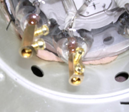
I stripped down some 10A butt-connectors and used the barrels directly on the tube pins, being careful not to twist them in case the glass cracked. The screws could be tightened easily with a long screwdriver through the opposite handily placed holes in the metal skirt.
Result – a fully working tube 🙂
The circuit
Following some further research, I have decided to try this circuit first as the one shown at the end of the page seems to be a bit radical in it’s design and probably not for suitable raw beginners. This one might not have the same output but it should be easier to get running and safer for the tube.

C2 – Filter cap, 1360pF 10kV ceramic.
C3 – Tank cap, 1880pF 20kV ceramic.
C4 – Grid cap, 1360pF 10kV ceramic.
C5 / C6 – Filament filters, 0.1uF 1000v polypropylene.
L1 – Primary coil, 25 turns insulated wire on a 150mm former.
L2 – Feedback coil, 20 turns insulated wire on a 150mm former, mounted 1cm below the primary coil, moveable for tuning.
L3 – Secondary coil, 1000 turns 0.315mm wire on a 68mm former.
L4 – Anode choke inductor, 10 turns close wound on R1.
R1 – Anode choke resistor, 100R 10W wirewound.
R2 – Grid leakage resistor, 5-10k 10W wirewound.
R3 – Screen bias resistor, 21k 40W wirewound.
V1 – GU-81M Tube.
In the circuit 1 above, the tube is wired as a pentode. The center tap of the filament is grounded to the RF ground system along with the base of the secondary and the zero volt supply rail.

C2 – Filter cap, 470pF 8kV ceramic.
C3 – Tank cap, 2040pF 20kV ceramic.
C4 – Grid cap, 1410pF 20kV ceramic.
C5 / C6 – Filament filters, 0.1uF 1000v polypropylene.
L1 – Primary coil, 48 turns insulated wire.
L2 – Feedback coil, 21 turns insulated wire.
L3 – Secondary coil, 1000 turns 0.25mm wire on a 68mm former.
L4 – Anode choke inductor, 10 turns close wound on R1.
R1 – Anode choke resistor, 100R 10W wirewound.
R2 – Grid leakage resistor, 500R 85W wirewound.
V1 – GU-81M Tube.
In circuit 2, the tube is wired as a triode and not a pentode, this makes it a bit easier to set up. The centre tap of the filament is grounded to the RF ground system along with the base of the secondary and the zero volt supply rail. The anode choke prevents VHF parasitic oscillations. C2 protects the power supply from spurious RF pulses on the supply rails
The power supply

Transformer – Microwave oven transformer, 2100v output.
C1 – Two microwave oven capacitors, total value around 2uF.
D1 – Two microwave oven diodes in series.
F1 – Variac protection fuse, around 5-10A.
This circuit has several different names – level shifter, voltage doubler etc. It outputs around twice the transformers voltage at halfwave dc, so I should be getting about 4-5kv out of it.
The secondary coil

The freshly wound secondary coil. The coil former is 68mm pvc pipe, dried, wound and varnished three times. As before, the winding jig was made up of junk box stuff, this time I used a battery operated drill to turn the former, which was much better. Total winding time was 30 minutes. Once wound, I switched back to the slow mains operated motor for the varnishing coats.
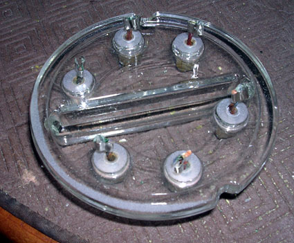
Tank capacitor

Four 470pF 20kV 60kVAr Capacitors, connected in parallel for a total value of 1880pF. They are quite large, the total length of the unit is around 420mm and weighs around 2kg !
I have connected them with 25mm x 1.5mm aluminium strips, hopefully they will be big enough for the job but who knows !!
The control box
I am using the same control box that was built for my spark gap coil as it was well built and can handle the current easily.

Test results 1
Lashing it together and first tests…
Thar she blows !! Not much, just 15mm, but oh so important !!
Probably the worst primary and feedback coils ever wound ! It just goes to show how wildly you can flaunt the basic design concepts and still get sparks.
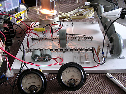
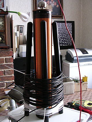
The birds nest ! A messy lash-up to get the ball rolling and find the weak spots in my design, stand well back ! The meters measure supply volts and current drawn.

Deep joy ! Happiness is a hot cathode !
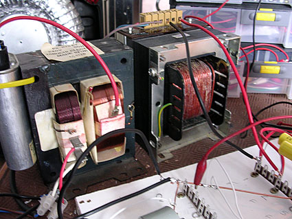
The two transformers, the right hand one is a 300w 24v supply for the heaters and on the left is the microwave oven transformer for the high voltage supply.
Test results 2
After a bit of tuning, results were improving. It was still running at 50v input because even at that low voltage, it was drawing 4A and my control box was only built for 5! Rebuilding the control box will have to be done next so that I can increase the power further.

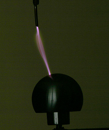
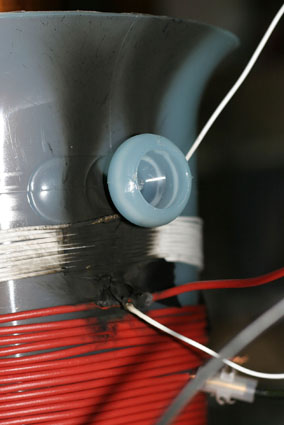
Brush discharges. Without an arc to draw the current, the high voltage charge escapes as a fine blue brush with a hissing noise. It likes sharp points, the lower discharge is coming from the edge of the metal tape holding the pin on. The upper discharge is from an earthed wire and is being drawn towards the pin.
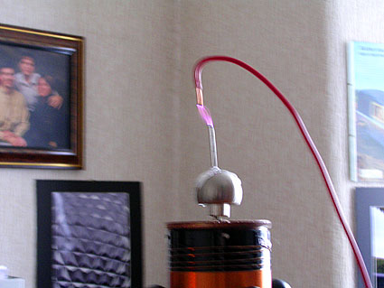
Arcs – A lovely 40mm arc, being drawn between an earthed wire and the discharge ball. It makes a deep crackling noise and generates a vast amount of heat. After 10 seconds, the plastic insulation on the earthed wire starts to melt.

Plasma. A poor 40w light bulb getting it’s gas ionised into plasma. This effect was created at only 20v input, any higher and the glass bulb gets too hot ! This is a very satisfying effect and the plasma can be attracted to the hand (carefully!) although even at this power, the glass still gets hot.
Test results 3
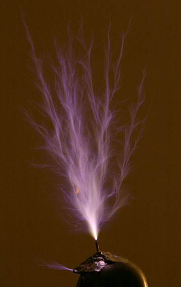
Feeling a bit bold, I removed the earthed wire target and turned the input up to the limit of my control box – about 110v at 5A. The long streamer running up to the top left is about 100mm long.
Test results 4
After getting a bit fed up with smalltime results, I decided to rebuild my power supply section. I am now running the plate and grid2 from separate, variac controlled microwave oven transformers, both running standard level shifter setups. This means that I have got much more than enough power to seriously thrash this thing ! I can now set the plate voltage at 2000v and then vary the output by turning the grid2 supply from 0 – 600v. The setup now looks like this…

The results speak for themselves! It now spits out 220mm streamers which look like daggers and hums like a power substation ! I have a bit more work to do yet but it’s getting there.

Above is a scope picture of the emmitted field around the coil with it running at near cut-off with no visible output. The signal was picked up with a 200mm antenna about 1 meter away from the coil as i don’t like getting the scope too near it.

This picture was taken using the same setup but with the coil emitting a 50mm discharge.
Test results 5
After a long period of being left sitting on the dining room table, I decided to warm the beast up again ! I wound a new primary set on a plastic ice bucket to increase the diameter a bit and prevent arc-over.
The new primary changed the output from long and thin to shorter, fatter sparks, probably due to different coupling values. It was now VERY loud and kept melting my breakout point on the topload. All was going well until…
You can’t ignore the acrid stench of burning insulation ! Oh dear !
There goes the ice bucket theory. I think what had happened is that, during its idle break, the coil fell over and was stood up again but I did not check the positions of the coil windings and connections before juicing it up with 2000vdc. Just goes to show that a 5mm gap is not good enough between the feedback coil and the primary coil. It probably was not being helped by the fact that the primary had excess turns on it which were acting as an open auto-transformer and stepping up the tank circuit voltage even more.